A Comparative Study on Accuracy of Different Surgical Guides to Determine the Positioning of the Implant Osteotomy Site- An Innovative In Vitro Study
- Anil Kumar Komuravelli , Professor and Head, Department of Prosthodontics, Saraswati Dhanwantari Dental College, and Hospital, Parbhani.
- Suraj Devichand Tambe , Reader, Department of Prosthodontics, Saraswati Dhanwantari Dental College, and Hospital, Parbhani
- Sneha Prakash Patil , Reader, Department of Oral Medicine and Radiology, Saraswati Dhanwantari Dental College, and Hospital, Parbhani
- Mahavir Sarnot , Senior Lecturer, Department of Conservative Dentistry and Endodontics, Rural Dental College, Loni BK
- Nilanjana Zende , Senior Lecturer, Department of Conservative Dentistry and Endodontics, Rural Dental College, Loni BK
- Antariksha V. Dod6 , Reader, Department of Prosthodontics, Saraswati Dhanwantari Dental College, and Hospital, Parbhani
Article Information:
Abstract:
Background: Aim: To evaluate and compare the accuracy of four different surgical guides in determining the accurate angulation and the position of the implant osteotomy site. Materials and Methods: A subject with missing mandibular left first molar with adequate height and width of residual ridge was chosen. Total, 24 casts of the subject were produced which were divided into 4 groups. Surgical guides such as 2 drill guiding stents, one hand piece guiding stent and a dual purpose stent without any drill guidance were fabricated using four different techniques over these casts. Intraoral periapical radiograph and Computed Tomography images were made to determine the optimum implant angulations. After osteotomy sites were prepared using these guides on the casts, guide pins were positioned in these sites and photographs in the mesio-distal and buccolingual view of the casts were made. The photographs were overlapped on the intraoral periapical radiograph and Computed Tomography images respectively. The angulations and linear measurements of osteotomy sites were then compared with the predetermined optimum angulations using an Adobe photoshop 9. One way ANOVA and Tukey’s Post-Hoc test were used for statistical analysis. Results: Drill guiding surgical stent proved to be precise with 1.18 to 1.55 degrees minimal discrepancy in angulation. Dual purpose stent was least accurate with 4.88+4.6 degrees discrepancy. When linear discrepancy was evaluated, drill guiding surgical stent proved to be accurate (0.4-0.49mm). Hand piece guiding stent was least accurate with 1.08 ± 0.72mm discrepancy. Conclusion: Drill guiding stents proved to be accurate in positioning the osteotomy site and could be used to position implants clinically. Clinical significance: The present study facilitated proper selection of a surgical guide which could guide ideal placement of implants clinically.
Keywords:
Article :
INTRODUCTION :
The use of implant surgical guides is often needed to facilitate optimal implant placement.[1] The ability to control and predict final implant position using surgical guide can be critical in establishing both the functional and esthetic goals.[2],[3] The present study evaluates and compares the accuracy of four different surgical guides in determining the accurate angulation and the position of the implant osteotomy site.
The need for precise placement of implants has led to the development of number of template designs.[4] Some designs are simpler, such as clear vacuum formed matrix with a hole drilled through in the desired position for the implant.[5] These are quick and easy to fabricate but may allow much flexibility in the final positioning of the implant which may lead to inaccuracy. Few designs incorporate metal tubes into the implant placement guide. These tubes restrict the positioning of the implant with less flexibility during placement procedure.[6],[7] Other designs include labial outline stent made from a wax-up of final restoration or a duplicate of existing restoration etc.[4]
Accurate radiographic data of the recipient sites and proper surgical guides are required to place implants in their predetermined position.[8] CT scans provide considerable information about the internal anatomy of the bone, which is invaluable in determining the position of the inferior canal and maxillary sinus.[9] Various template designs differ in their accuracy in proper positioning of the implants which in turn minimizes loading forces and facilitates an implant supported restoration with a satisfactory function, esthetics and hygiene outcome. Very few attempts have been made to evaluate the precision of surgical placement utilizing various laboratory processed surgical guides. [10]
The hypothesis of the present in-vitro study was that the drill guiding stents are the most accurate among all the surgical guides used.
MATERIALS AND METHODS:
Ethics: This in vitro study was completely performed on the patient’s plaster models except the dental impressions.
A subject with missing mandibular left first molar with adequate height and width of residual ridge was chosen. Radiographically, the height of the bone was 12.5 mm above the inferior alveolar canal and buccolingual width of 7 mm. The mesiodistal width of the edentulous span was 10.5 mm. Elastomeric impressions (Dentsply, Caulk, USA) of maxillary and mandibular arches were made and poured in Dental Stone (Kalstone, Kalabhai Karson Pvt. Limited, Mumbai, India). Patient’s casts were mounted on a Hanau Wide-Vue articulator (Teledyne, Water Pik Technologies,Inc. Fort Collins, CO, USA) using Hanau Spring-Bow (Teledyne, Water Pik Technologies,Inc. Fort Collins, CO, USA) face-bow transfer. Diagnostic wax-up for missing 36 was made. [4],[12],[9],[13] A diagnostic stent was fabricated with a clear sheet of vacuum formed material on the duplicated cast obtained from diagnostic wax-up [Figure 1]. The stent incorporated: [12],[13]
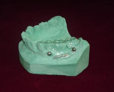
Figure 1: Diagnostic stent with steel spheres and gutta percha cones
· Two steel spheres placed buccally, each on the adjacent tooth area (they are used during CT imaging).
· Two gutta percha points were placed longitudinally along the edentulous space on the buccal and lingual surface of the stent (they are used during IOPA radiograph).
· Zinc oxide eugenol cement was filled in the tooth space created in the stent for missing 36.
With the stent in position in the oral cavity, an IOPA radiograph using long cone technique was made (gutta percha markers were removed at this stage). [12],[14],[15],[16] Before performing the radiography, a putty index was made by placing putty material between the occlusal surfaces of the teeth and bite block of XCP (Extension Cone Paralleling) device. This index along with the XCP device helped to maintain the same angulation for photographic camera later. The IOPA was scanned and the optimum mesiodistal angulation of the proposed implant was then plotted taking into consideration the occlusal plane and long axis of the adjacent teeth [Figure 2- a]. [15],[16]
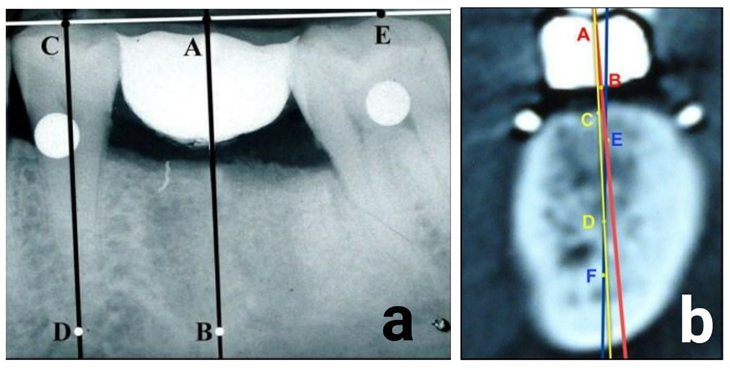
Figure 2- a: AB- Optimal mesiodistal angulation of the implant plotted on radiograph
CD - long axis of anterior tooth, CE - occlusal plane.
b: CD- Optimal implant trajectory in buccolingual direction. EF- Bone trajectory, AB- Prosthetic trajectory
With the stent in position in the mouth, a coronal section CT of the mandible in edentulous area was made (steel spheres were removed at this stage). CT image showed two radiopaque gutta percha markings and radiopacity of ZOE filled tooth form. The CT image was analyzed for implant trajectory using Adobe photoshop, version 9. The lines plotted were bone trajectory (EF) and prosthetic trajectory (AB) through which an implant trajectory (CD) was obtained [Figure 2- b]. [17]
From the existing elastomeric impression of mandibular arch, another stone cast was obtained. Steel spheres and gutta percha points were transferred from the radiographic stent onto this cast. The obtained cast with markers on them was used for the fabrication of silicone mold. This mold was used to produce 24 casts necessary for the fabrication of four different types of surgical templates, six of each type used in this study.
Procedure for Surgical guide 1 fabrication [1]: Drill guiding stent [Figure 3- a]
i) On the diagnostic cast, proposed implant site was located on the ridge crest by marking a line 4mm lingual to the proposed buccal extent of the completed crown. The mesiodistal center located on this line represented the proposed implant site.
ii) A hole was drilled on the cast at a desired implant angulation using a surveyor at the proposed implant site.
iii) A drill blank of same diameter was placed in the drilled hole and auto polymerizing resin material was then adapted to the lingual aspect of the blank. Resin was also adapted on occlusal and lingual surfaces of adjacent teeth.
iv) After polymerization, guide was removed from cast and trimmed as necessary. Three guides with increasing diameter of the channel which were useful for sequential enlargement of osteotomy site, were prepared.
Procedure for Surgical Guide 2 fabrication [18]: Dual purpose stent [Figure 3- b]
i) Diagnostic wax-up of the missing tooth was completed and was duplicated to produce another cast. Vacuum formed clear template (1.5mm thickness) was fabricated over it.
ii) Then on the original cast optimum position of the implant was marked. 2 mm diameter hole was cut through the occlusal surface of template so that the hole coincided with the implant site on the ridge.
iii) A line was drawn on the side of the cast which represented the vertical direction in which implant was to be placed. Gutta percha cone was placed on the facial surface of template along the marked line on the cast and secured with sticky wax.
iv) The template was then radiographically evaluated for proposed osteotomy site position and then changes in the location of hole was made accordingly.
Procedure of Surgical Guide 3 fabrication [19]: Drill guiding stent [Figure 3-c]
i) Diagnostic wax-up of missing tooth was made on the cast. Impression of the waxed up cast was made and two casts were poured. Vacuum formed clear template was fabricated on one cast and on the other cast, the tooth was cut off where the implant would be placed.
ii) The fabricated vacuum formed template (0.5mm thickness) was placed on the cast where tooth was cut off and hole was made on its occlusal surface. Cast along with the template was placed on the surveyor table to determine appropriate implant angulation.
iii) Using a slow speed hand piece attached to the surveyor, a hole was drilled in the cast where the implant had to be placed. A guide pin was positioned in the drilled hole.
iv) A brass tube with 4.5mm diameter was made to slide over the guide pin and then sealed to the template with orthodontic resin. Later, 3.5mm, 2.5mm diameter tubes were slipped inside the larger tube.
Procedure for Surgical Guide 4 fabrication [6]: Hand piece guiding stent [Figure 3-d]
i) A hole was drilled into the cast using the round bur at the planned implant position, aligning the bur at a desired angulation of the implant.
ii) A wooden stick was made to slide into the hole and stabilized with self- cure acrylic resin. A hand piece head was positioned over it.
iii) Auto polymerizing custom tray material was adapted over the occlusal and lingual surfaces of the teeth adjacent to the surgical site and a guide was formed for hand piece by adapting around its head in the missing area.
iv) Walls of the guide were contoured to correct dimensions. A line parallel to the wooden stick was drawn on the wall of the guide.
v) A small portion of auto polymerizing rope was adapted around the wooden stick. This would create an opening through which osteotomy site could be marked or a dimple created on bone before site preparation.
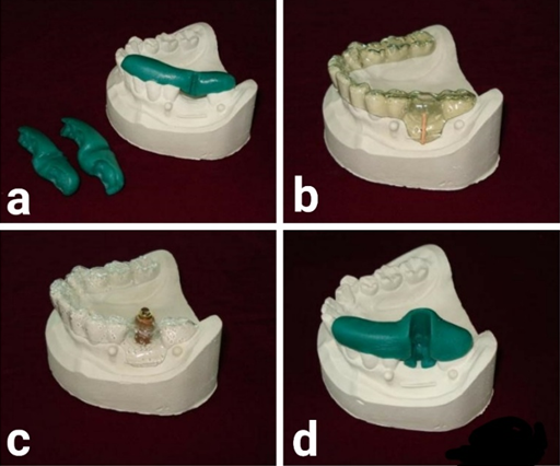
Figure 3-a: Drill guiding stent (guide 1)
b: Dual purpose stent (guide 2)
c: Drill guiding stent (guide 3)
d: Hand piece guiding stent (guide 4)
Preparation of osteotomy site:
Four custom made drills were fabricated using commercially available high speed steel (HSS) drills. The final drills used were 2.5mm, 3.4mm, 4.4mm wide and the length 20mm. This facilitated the sequential enlargement of the osteotomy site.[14] Contra angle NSK micromotor hand piece was used to prepare osteotomy site. Since the mesiodistal space between adjacent teeth was 10.5mm, single implant with 5 mm diameter implant was preferred.[16] Keeping in mind, an implant diameter of 5 mm, the osteotomy site was prepared with the diameter of 4.4 mm and length 10 mm in all the 24 casts using the 4 types of surgical guides.
A paralleling pin was placed in the osteotomy site. The putty index (obtained during the long cone technique) was placed on the occlusal surface of the teeth of the cast, and XCP device secured on the indentation formed in the putty index. The camera was positioned near the ring of the XCP device similar to the placement of the cone of x-ray machine, so that the camera focuses through the ring. This would standardize the angulation from where radiograph and digital photo were taken. Lateral photographs of all the 24 casts with osteotomy sites were obtained with paralleling pin in position [Figure 4-a]
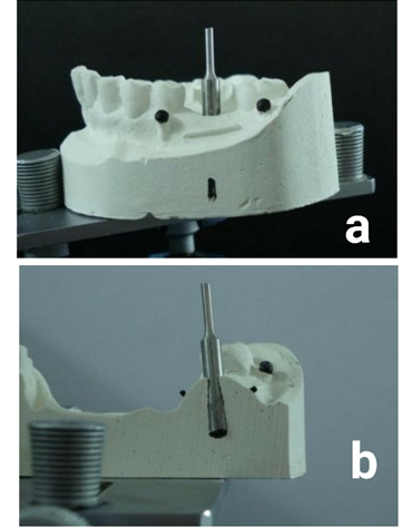
Figure 4-a: Lateral photograph of the cast with paralleling pin in the osteotomy site.
b: Photograph of the sectioned cast with paralleling pin in the osteotomy site.
The casts were then sectioned buccolingually to expose the osteotomy site half the way. After sectioning of the cast, a photograph of the sectioned cast was made in such a way that the camera was placed perpendicular to the cut section [Figure 4-b]. The same position was maintained for photographs of all the casts.
Photographic method to assess the mesiodistal and buccolingual angulations of the osteotomy site:
The digital photographs were then overlapped with the IOPA in Adobe Photoshop 9 software programme [Figure 5-a]. [20] Steel sphere images were used as a guide to overlap both the images. After overlapping, predetermined mesiodistal angulation on the IOPA either intersected or coincided with the angulation of the paralleling pin. The angle between the lines depicted the amount of discrepancy. Discrepancies for all mesiodistal angulations obtained using 4 types of surgical guides were measured.
The sectioned cast photographic images were overlapped with the CT images [Figure 5-b]. Gutta percha markings in photographs and the CT images were used as a guide to overlap the images. The predetermined buccolingual implant angulation intersected or coincided with the buccolingual angulation of the osteotomy sites. The angle formed between the 2 lines depicted the amount of discrepancy. Discrepancies for all the buccolingual angulations obtained using 4 types of surgical guides were measured. All the measurements were made using standard photographic setup.
Statistical analysis: The Mean, Standard Deviation of angular and linear parameters were calculated for all the types of surgical guides. One-way ANOVA was used to calculate the significance of variation. Tukey’s Post-Hoc test was used to analyze the significance of pairwise difference between the groups with the p value of 0.05 level of significance.
RESULTS:
With respect to mean of the mesiodistal and buccolingual angles formed between the predetermined implant position and osteotomy sites, surgical guide 1,2,3,4 showed a discrepancy of 1.18+0.68 degrees (mean + SD), 4.88+4.63 degrees (mean + SD), 1.55+0.71 degrees (mean + SD) and 3.58+2.76 degrees (mean + SD) respectively [Table 1]. The difference was statistically significant (p<0.05). Pairwise differences showed that there was a statistically significant difference between groups I-II and II-III.
Table 1: Mean of mesiodistal and buccolingual discrepancies in angulations in study Groups
|
Study Groups |
Mean ± SD |
F* Value |
Significance |
Significant Groups # |
|
Surgical guide 1 |
1.18 ± 0.68 |
4.84 |
P<0.05 Significant |
I & II, II & III |
|
Surgical guide 2 |
4.88 ± 4.63 |
|||
|
Surgical guide 3 |
1.55 ± 0.71 |
|||
|
Surgical guide 4 |
3.58 ± 2.76 |
|||
|
|
|
|
|
|
|
* One way ANOVA |
|
|
|
|
|
# Tukey's Test |
|
|
|
|
|
There was no significant difference between I&III, I&IV, II & IV, III&IV |
||||
With respect to mean of the mesiodistal and buccolingual linear measurements obtained between the standard implant position and achieved osteotomy sites at entry point for surgical guide 1,2,3 and 4 were 0.49+0.31mm (mean + SD), 0.92+0.861mm (mean + SD), 0.4+0.27mm
(mean + SD) and 1.08+0.72mm (mean + SD) respectively [Table 2]. The difference was statistically significant (p<0.05). Pairwise differences showed that there was a statistically significant difference between groups III-IV.
When angulations of osteotomy sites were evaluated, drill guiding surgical stents proved to be accurate (with 1.18 to 1.55 degrees discrepancy). Dual purpose stent was least accurate with 4.88+4.6degrees discrepancy. When linear discrepancy was evaluated, drill guiding surgical stents proved to be accurate (0.4-0.49mm). Hand piece guiding stent was least accurate with 1.08 ± 0.72mm discrepancy.
Table 2: Mean of mesiodistal and buccolingual linear discrepancies in measurements in study Groups
|
Study Groups |
Mean ± SD |
F* Value |
Significance |
Significant Groups # |
|
Surgical guide 1 |
0.49 ± 0.306 |
3.66 |
P<0.05 Significant |
III & IV |
|
Surgical guide 2 |
0.92 ± 0.861 |
|||
|
Surgical guide 3 |
0.40 ± 0.266 |
|||
|
Surgical guide 4 |
1.08 ± 0.72 |
|||
|
|
|
|
|
|
|
*One way ANOVA |
|
|
|
|
|
# Tukey's Test |
|
|
|
|
DISCUSSION :
The present study showed an innovative technique to compare the efficacy of various surgical guides for implant placement. The errors in magnification and the angulations of the images were avoided using the image overlapping technique.
CT scan and IOPA radiograph using long cone technique were used in this study to obtain the standard implant angulations. CT images are very accurate and a detailed image of areas with missing teeth could be obtained.[21] Long cone periapical radiographs provided minimally distorted images of edentulous space and adjacent teeth.[21] In the preprosthetic phase, periapical films are most often used for single tooth implants in regions of abundant bone width.[16] Radio-opacities of steel spheres in the IOPA radiograph were overlapped with the replica of steel spheres present on the cast in the photographic images. Similarly, gutta percha opacities in the CT image were overlapped with the replica of gutta percha points present on the cast in the photographic images. Thus, prevention of rotation and magnification errors during overlapping was possible.
Very few studies have compared the efficacy of surgical guides for implant placement. A similar study was conducted to measure the divergence between planned implant and actual surgical placement, using a simulated clinical scenario, and comparing CAD/CAM surgical guide with a conventionally produced guide. Conventional guides allowed for an accuracy of 8+4.5 degrees and stereolithographic guides achieved an accuracy of 4.5+2 degrees.[11] In the present in-vitro study, the accuracy ranged from 1.18+0.68 degrees to 4.88+4.63 degrees for various surgical guides.
The accuracy of two methods for computerized tomography (CT) - guided template production via a surgical navigation system was studied. The mean accuracy for both the methods was 0.5+0.3mm and 0.6+0.3mm.[23] Another study evaluated the angulation of the implants using a specific surgical template. The average angle difference between the proposed and actual directions of the implant was 5.0 degrees. [22]
The degree of difference between the proposed and achieved implant directions may be influenced by various factors: the construction accuracy of the template, the surgical accuracy using the templates, the accuracy of the study model, and the measurement accuracy.
Accuracy of the study model was standardized by using a silicone mold. This mold was used for fabrication of all the required 24 models for the study. Single operator had constructed the templates and prepared osteotomy sites in the models. Thus the construction accuracy and surgical accuracy were maintained. Measurement accuracy was standardized by making each reading thrice and taking the mean of them.
The main advantages of this evaluation system were: it facilitated proper selection of a surgical guide which could guide ideal placement of implants clinically. It was easy to perform a comparative analysis. It was a cost effective technique and any number of surgical guides could be compared.
Limitations of the study were few. The density of the cast may not match to the density of the bone in vivo. This could create minor variation in the values obtained on the cast in comparison to intra oral values. Drills used in the study were of industrial purpose. The cutting efficiency might vary compared to the implant drills used intra-orally. Similar methodology on large samples is warranted for better determination of the precise surgical guides.
CONCLUSION:
Drill guiding stents (surgical guides 1 and 3) showed to be more accurate when compared to dual purpose stent (surgical guide 2) and hand piece guiding stent (surgical guide 4). The present method of evaluation of accuracy of surgical guides was effective, easier and less expensive.
Clinical significance:
Proper selection of a surgical guide was possible which could facilitate easy placement of implant clinically. The accuracy of placement implant clinically could be improved drastically with drill guiding stents used in the study.
REFERENCES:
1. Shotwell JL, Billy EJ, Wang H, Oh T. Implant surgical guide fabrication for partially edentulous patients. J Prosthet Dent 2005;93:294-297.
2. Parel SM, Funk JJ. The use and fabrication of a self-retaining surgical guide for Controlled implant placement: A Technical note. Int J Oral Maxillofac Implants 1991;6: 207-210.
3. Umapathy T, Jayam C, Anila B S, Ashwini C P. Overview of surgical guides for implant therapy. J Dent Implant 2015;5:48-52.
4. Higginbottom FL, Wilson T G. Three dimensional templates for placement of root-form Dental implants: A Technical note. Int J Oral Maxillofac Implants. 1996;11:787-793.
5. D’Souza K M, Aras M A. Types of implant surgical guides in dentistry: A review. Journal of Oral Implantology 2012;38:643-652
6. Windhorn RJ. Fabrication and use of a simple implant placement guide. J Prosthet Dent 2004;92:196-199.
7. Ramasamy M, Giri, Raja R, Subramonian, Karthik, Narendrakumar R. Implant surgical guides: From past to the present. J Pharm Bioallied Sci. 2013 Jun;5( 1):98-102.
8. Cehreli MC, Calis CA, Sahin S. A dual purpose guide for optimum placement of dental implants. J Prosthet Dent 2002;88:640-643.
9. Sethi A. Precise site location for Implants using CT Scans: A Technical note. Int J Oral Maxillofac Implants 1993; 8:433-438.
10. Mora M A, Chenin D L, Arce R M. Software tools and surgical guides in dental implant guided surgery. Dental Clinics 2014;58(3):597-626.
11. Sarment DP, Sukovic P, Clinthrone N. Accuracy Of Implant Placement With A Stereolithographic Surgical Guide. Int J Oral Maxillofac Implants 2003;18:571-577.
12. Kopp KC, Koslow AH, Abdo OS. Predictable implant placement with diagnostic surgical template and advanced radiographic imaging. J Prosthet Dent 2003; 89:611-615.
13. Koyanagi K. Development and clinical application of a surgical guide for optimal implant placement. J Prosthet Dent 2002; 88: 548-552.
14. Sario FD. A system for the diagnosis, placement, and prosthetic restoration of root form implants (U.S. patent #5,769,636). J Prosthodont 2003; 12: 2-7.
15. Cranin NA. Atlas of Oral Implantology. 2nd ed, St. Louis: Mosby; 1995. pp.30-33.
16. Misch CE. Contemporary Implant Dentistry. 2nd ed. St. Louis: Mosby; 1999. pp.74-5,421-5.
17. Nevins M, Mellonig JT(eds). Implant Therapy, Clinical Approaches and Evidence of Success, Vol 2. Chicago, Quintessence; 1998. pp.39-43.
18. Shahrasbi HA, Hansen CA. Surgical oral radiographic guide with a removable component for implant placement. J Prosthet Dent 2002;87:330-332.
19. Becker CM, Kaiser DA. Surgical guide for implant placement. J Prosthet Dent 2000;83:248-251.
20. Di Giacomo GAP, Cury PR, Araujo NSD, Sendyk WR, Sendyk CL. Clinical application of stereolithographic surgical guides for implant placement: preliminary results. J Periodontol 2005;76:503-507.
21. Hobkirk JA, Watson RM, Searson LJJ. Introducing Dental Implants. London: Churchill Livingstone; 2003. pp.101-106.
22. Naitoh M, Ariji E, Okumura S, Kurita K, Ishigami T. Can implants be correctly angulated based on surgical templates used for osseointegrated dental implants? Clin Oral Impl Res 2000;11:409-414.
23. Widmann G, Widmann R, Widmann E, Jaschke W, Bale R. Use of a surgical navigation system for CT guided template production. Int J Oral Maxillofac Implants 2007;22:72-78.